Precision Casting Defects: How to Identify, Prevent and Fix Common Issues
Precision casting defects are the foundry’s primary quality adversary — hidden inside components that may look perfect externally but contain voids, cracks, or discontinuities that will cause premature failure under structural load, fatigue cycling, or pressure. Understanding each defect type — how it forms, how it is detected, and how it is prevented — is essential knowledge for every engineer specifying or procuring investment castings.
At Uni Tritech, India’s NADCAP-certified aerospace investment casting foundry, our quality engineers and metallurgists use a systematic defect prevention and detection approach covering process control, DFM review, real-time monitoring, NADCAP NDT inspection, and root cause analysis. This comprehensive guide covers the seven most common precision casting defects — with identification, prevention, and remediation for each.

Why Precision Casting Defects Must Be Taken Seriously
Investment casting defects in aerospace, defence, medical, and space applications are not warranty problems — they are safety-critical failures. A turbine blade with sub-surface shrinkage porosity can fracture at operating temperature, destroying a jet engine. A surgical implant with a surface crack can fracture in vivo, requiring revision surgery. A rocket engine nozzle with a cold shut can fail on ignition.
Uni Tritech’s NADCAP-certified process is built on a zero-defect culture. Every casting undergoes 100% NDT inspection — X-ray radiography for internal defects and FPI for surface defects — with documented rejection and rework procedures aligned to prime contractor and NADCAP quality requirements. This guide shares our expertise to help customers understand and specify defect acceptance criteria correctly.
1. Gas Porosity: Cause, Detection and Prevention
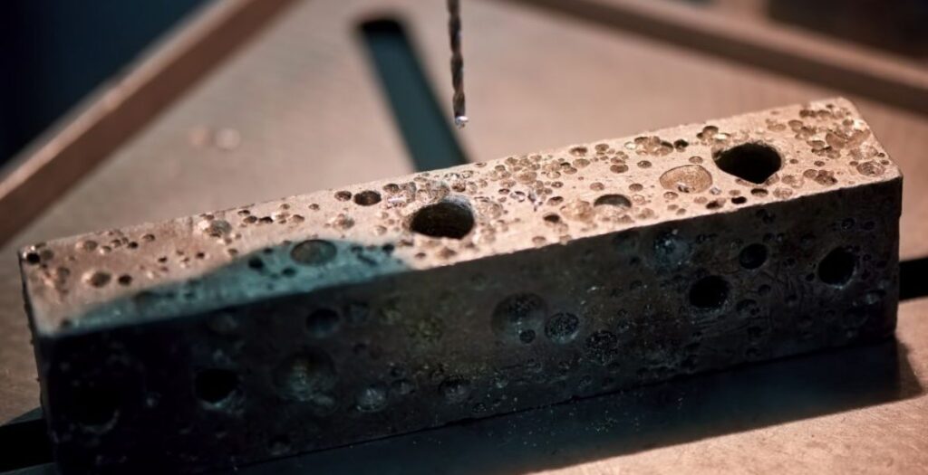
Gas porosity is the most common precision casting defect — forming when dissolved gases (primarily hydrogen in aluminium alloys, nitrogen and CO in steel alloys) come out of solution during solidification, creating spherical voids trapped within the casting wall.
Gas Porosity Identification:
- X-ray appearance: rounded, smooth-edged voids of 0.1–5 mm diameter; isolated or clustered depending on severity.
- Location: typically distributed throughout the casting cross-section; more concentrated in last-to-solidify regions.
- ASTM E155 reference: gas porosity evaluated against ASTM E155 reference radiographs for aluminium; ASTM E192 for superalloy castings.
Gas Porosity Prevention:
- Vacuum melting: melt under vacuum (VIM) eliminates dissolved gas pickup — mandatory for nickel superalloy and titanium castings.
- Alloy degassing: aluminium alloys degassed using rotary degassing with inert gas purge before pouring to reduce hydrogen content.
- Pouring speed control: controlled pour rate avoids turbulence that entrains air — slow, bottom-filling pour is preferred.
- Mold and core drying: ceramic shell must be fully dried and pre-heated before pouring to prevent moisture-generated steam porosity.
2. Shrinkage Defects: Cause, Detection and Prevention
Shrinkage is the second major category of precision casting defects — forming because metals contract during solidification. When a casting solidifies non-uniformly, the last-to-solidify sections cannot draw liquid metal from already-solidified regions, creating voids. Macro-shrinkage produces large visible cavities; micro-shrinkage (also called dendritic shrinkage) produces fine interdendritic porosity.
Shrinkage Defect Identification:
- X-ray appearance: macro-shrinkage appears as irregular, angular voids in thick sections; micro-shrinkage as a diffuse cloudy region.
- Location: invariably in the last-to-solidify region — geometric hot spots, isolated thick sections, junction of ribs to walls.
- DFM correlation: shrinkage almost always occurs in sections that violate DFM wall uniformity rules — a direct DFM failure indicator.
Shrinkage Defect Prevention:
- DFM compliance: uniform wall thickness and smooth transitions in component design eliminate the hot spots that cause shrinkage.
- Riser optimisation: correctly sized and located risers supply liquid metal to compensate for solidification shrinkage.
- Chill placement: external or internal chills accelerate solidification of thick sections, eliminating hot-spot shrinkage.
- HIP treatment: Hot Isostatic Pressing closes micro-shrinkage porosity by applying high pressure at temperature — used widely for aerospace castings.
3. Cold Shuts: Cause, Detection and Prevention
Cold shuts are surface or near-surface precision casting defects forming when two streams of metal meet during mold filling but fail to fully fuse — creating a linear discontinuity. Cold shuts appear as smooth-edged linear indications on the casting surface and indicate that metal has lost too much superheat before the mold was completely filled.
Cold Shut Identification:
- Visual appearance: smooth-edged linear surface mark or seam that does not penetrate deeply — easily confused with a crack.
- FPI detection: cold shuts that break the surface are clearly revealed by fluorescent penetrant inspection (FPI) as linear indications.
- X-ray appearance: cold shuts show as linear features near the surface — distinguish from hot tears by location and morphology.
Cold Shut Prevention:
- Pouring temperature: increase superheat (pouring temperature above liquidus) ensures metal flows to fill thin sections before freezing.
- Gate and runner optimisation: correctly sized gates and runners ensure mold fills rapidly before metal cools — simulation-verified gating design.
- Minimum wall thickness: sections thinner than DFM minimum wall for the alloy are prone to cold shuts — correct in design before tooling.
4. Hot Tears: Cause, Detection and Prevention
Hot tears are solidification cracks forming at elevated temperature when the partially solidified casting is constrained from contracting freely. Hot tears are the most dangerous precision casting defects because they propagate through the casting wall and cannot always be repaired — they typically result in scrap.
Hot Tear Identification:
- Visual/FPI: branching, irregular crack-like indication at the casting surface, often with an oxidised appearance.
- X-ray appearance: irregular, branching linear features in constrained locations — junctions of ribs, sharp corners, sudden thickness changes.
- Location: always in constrained regions where solidification contraction is resisted — a direct DFM indicator.
Hot Tear Prevention:
- Design corners: generous fillet radii eliminate stress concentration during solidification contraction — minimum 1.5 mm at all junctions.
- Shell compliance: engineered ceramic shell systems with designed-in compliance allow casting to contract without tearing.
- Alloy selection: alloys with wide freezing ranges (e.g. some stainless grades) are more susceptible — alloy selection for hot tear resistance.
5. Inclusions: Cause, Detection and Prevention
Inclusions in investment castings are foreign particles — ceramic shell fragments, slag, oxide films, or refractory contamination — entrapped within the casting. Inclusions are hard, brittle, and act as stress raisers in service, nucleating fatigue cracks in dynamic applications.
Inclusion Identification:
- X-ray appearance: high-density inclusions (ceramic, refractory) appear as bright spots on the radiograph; oxide films as irregular patches.
- Cross-section: metallographic examination reveals inclusion morphology, composition, and origin — essential for root cause analysis.
Inclusion Prevention:
- Ceramic shell integrity: rigorous shell quality control prevents shell spalling and ceramic fragment inclusion during pouring.
- Filter use: ceramic foam filters in the gating system trap slag and oxide before metal enters the mold cavity.
- Melt cleanliness: correct melting practice — skimming, vacuum melting, and clean charge materials — minimises oxide inclusion formation.
6. Dimensional Deviation and
7. Surface Roughness Defects
Dimensional deviation occurs when a casting measures outside drawing tolerance — caused by wax die wear, wax distortion, ceramic shell cracking, or insufficient shrinkage allowance in die design. Surface roughness defects (Ra exceeding specification) result from shell surface deterioration, contaminated shell systems, or post-cast damage.
- Dimensional deviation prevention: regular wax die inspection, shrinkage allowance verification, and CMM first-article inspection on each tooling set.
- Surface roughness prevention: fresh, well-maintained ceramic shell primary slurry; correct wetting of complex wax pattern surfaces; controlled shell drying.
- In-process dimensional monitoring: CMM measurements at key manufacturing stages (after wax injection, after first article) catch drift before it reaches production.
Defect Remediation: What Can Be Fixed?
Not all precision casting defects result in scrap. Repair options depend on the defect type, location, severity, and whether the customer’s specification permits repair:
- Weld repair: surface porosity and cold shuts in non-fracture-critical areas may be weld repaired per approved weld repair procedure.
- HIP treatment: micro-shrinkage and sub-surface porosity in forgeable alloys can be closed by Hot Isostatic Pressing — NADCAP HT required.
- Blending: minor surface imperfections within dimensional tolerance may be blended and re-inspected per engineering disposition.
- Scrap: hot tears, large macro-shrinkage, deep cold shuts, and high-density inclusions in fracture-critical locations — these are scrapped.
Frequently Asked Questions
The seven most common precision casting defects are gas porosity, shrinkage porosity, cold shuts, hot tears, inclusions, dimensional deviation, and surface roughness defects — each with different causes, detection methods, and prevention strategies.
Investment casting porosity is detected by X-ray radiographic inspection — gas porosity appears as rounded voids; shrinkage as irregular dendritic voids. NADCAP-certified radiography evaluates against ASTM E155 or E192 reference radiograph acceptance criteria.
Shrinkage defects form when isolated thick sections solidify last and cannot draw liquid metal from already-solidified regions — creating voids. Causes include non-uniform wall thickness, undersized risers, and incorrect DFM design violating wall uniformity rules.
Some precision casting defects can be repaired: surface porosity by approved weld repair; micro-shrinkage by HIP treatment; minor surface marks by blending. Hot tears, macro-shrinkage, and fracture-critical inclusions typically require the casting to be scrapped.
A cold shut is a precision casting defect forming when two metal streams meet during mold filling but fail to fully fuse — creating a linear surface discontinuity. Prevented by increasing pouring temperature and optimising gating system design.
HIP (Hot Isostatic Pressing) applies simultaneous high temperature (up to 1200°C) and high pressure (up to 200 MPa) to close micro-shrinkage porosity by solid-state diffusion bonding, significantly improving fatigue life of aerospace castings.
Uni Tritech prevents precision casting defects through: DFM review before tooling, vacuum melting, optimised gating simulation, NADCAP heat treatment, and 100% X-ray and FPI inspection on all aerospace castings before despatch.
Experiencing precision casting defects with your current supplier? Uni Tritech’s NADCAP-certified team can audit your casting design and process, identify root causes, and deliver zero-defect castings. Contact us today.