ET Now Machinist Awards 2025: Uni Tritech Recognized for Supply Chain Excellence
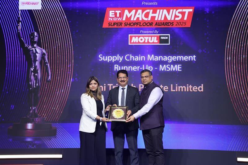
Uni Tritech Private Limited has been recognized as the Runner-Up in the Supply Chain Management (SCM) – MSME category at the 11th ET Now Machinist Super Shopfloor Awards 2025, an initiative by The Times Group. This prestigious recognition highlights Uni Tritech’s excellence in operational efficiency, manufacturing precision, and supply chain resilience. The award reflects the company’s strong commitment to quality, innovation, and delivering high-performance components for critical industries such as aerospace and defence. This achievement further strengthens Uni Tritech’s position as a trusted manufacturing partner in India and globally.
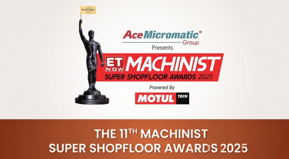
About ET Now Machinist Super Shopfloor Awards 2025
The ET Now Machinist Super Shopfloor Awards is one of India’s most respected platforms recognizing manufacturing excellence, innovation, and operational performance across industries.
Organized by The Times Group
Recognizes top-performing MSMEs and large manufacturers
Evaluates companies based on efficiency, innovation, and supply chain performance
Covers industries including aerospace, defence, automotive, and heavy engineering
The 2025 edition brought together industry leaders, innovators, and manufacturers who are shaping the future of India’s industrial ecosystem.
Uni Tritech’s Achievement in SCM Excellence
Uni Tritech Dharwad facility was selected as Runner-Up in the Supply Chain Management (SCM) – MSME category after a rigorous evaluation by industry experts and jury members.
This recognition highlights:
Strong supply chain systems
Operational agility
Consistent product quality
Ability to serve critical industries
The award reflects the collective effort of the entire Uni Tritech team in building a resilient and efficient manufacturing ecosystem.
What Makes This Recognition Significant
Winning at the ET Now Machinist Awards is not just an achievement—it is a validation of Uni Tritech’s manufacturing philosophy.
Operational Excellence: The company has built strong internal systems that ensure seamless production, efficient resource utilization, and timely delivery across projects.
Supply Chain Resilience: Uni Tritech has demonstrated the ability to maintain uninterrupted supply chains, even in complex and demanding manufacturing environments.
Industry Trust: Serving sectors like aerospace and defence requires strict compliance and reliability, which this recognition strongly validates.
Leadership & Team Contribution
The award was received by Mr. Madhu Shivangi, Chief Operating Officer, representing Uni Tritech at the ceremony held in New Delhi.
This moment highlights:
Strong leadership direction
Skilled engineering workforce
Cross-functional collaboration
Continuous improvement culture
The achievement belongs to every individual contributing to Uni Tritech’s success.
Event Highlights
📅 Date: 26th June 2025
📍 Venue: Roseate House, Aerocity, New Delhi
🕒 Awards Ceremony: 5:30 PM onwards
🏆 Category: SCM – MSME
The event also included the ET Now Machinist Tech Summit, bringing together thought leaders and industry experts.